BW–3dB = 2'760 Hz ; BW–60dB = 11'520 Hz ; f0 = 9.998'530 MHz

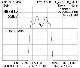
As it was remarked in the previous example, there is always a difference between the calculated filter response and the results of measurements. The main reasons are errors in determining the crystal equivalent parameter, wrong capacitance values and crystal mismatch.
Measuring the series and parallel resonance of a crystal it's not easy and it's very hard to tell the exact frequency of a maximum or a minimum within a few Hz. Unfortunately, when calculating Cs, a little change in the frequencies yields in significant changes in the result.
The simulator calculates theoretical values of capacitance that in practice are rounded and approximated to close values. The exact capacitance of a real capacitor can vary from one capacitor to another ad is function of the temperature. Also stray capacitance can play a role, especially when capacitor values are small, since the capacitors will "look bigger" by a few pF. Using capacitive trimmers could be a solution, but it's very hard to adjust the trimmers for the best response.
Finally, even if all crystals look identical, come out of the same stock and have been selected to have close resonance frequency, they are not identical and this will always produce higher ripple in the pass-band.
Trying to manually guess capacitor values is a nightmare since there are too many adjustments to make, but it's quite easy to tune a filter in order to make the pass-band wider or narrower. The idea is to keep the ratio between all the capacitors and just multiply all the capacitance values by a factor. Increasing the capacitance will make the bandwidth narrower and decreasing the capacitance will make the bandwidth wider. The bandwidth will not change symmetrically since the right side changes much more than the left one. Keep in mind that scaling capacitor values will also change the characteristic impedance of the filter and a different matching will be required (see below). Changing the ratio between the capacitors is generally not a good idea, since this will completely change the filter response and usually yields to significant ripple in the pass-band.
The following table summarizes the changes in the filter response by scaling capacitors. For simplicity, all the filters are directly connected to 50 Ω and this explains high pass-band ripple in wide filters. All filters are four poles Tchebycheff.
CS1 = CP2 = 120 pF ; CP1 = 100 pF
BW–3dB = 2'760 Hz ; BW–60dB = 11'520 Hz ; f0 = 9.998'530 MHz


CS1 = CP2 = 150 pF ; CP1 = 120 pF
BW–3dB = 2'360 Hz ; BW–60dB = 9'920 Hz ; f0 = 9.998'270 MHz
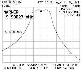

CS1 = CP2 = 220 pF ; CP1 = 180 pF
BW–3dB = 1'580 Hz ; BW–60dB = 8'260 Hz ; f0 = 9.997'760 MHz
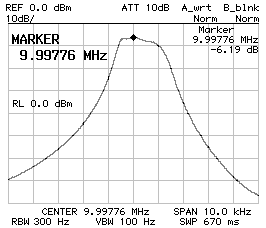
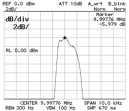
CS1 = CP2 = 390 pF ; CP1 = 330 pF
BW–3dB = 960 Hz ; BW–60dB = 5'540 Hz ; f0 = 9.997'480 MHz
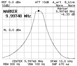
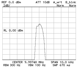
CS1 = CP2 = 470 pF ; CP1 = 390 pF
BW–3dB = 760 Hz ; BW–60dB = 4'940 Hz ; f0 = 9.997'340 MHz
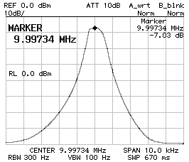
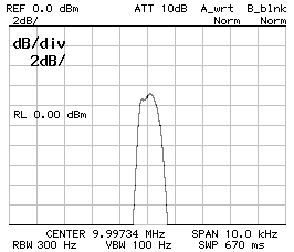
CS1 = CP2 = 560 pF ; CP1 = 470 pF
BW–3dB = 660 Hz ; BW–60dB = 4'440 Hz ; f0 = 9.997'270 MHz
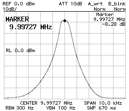
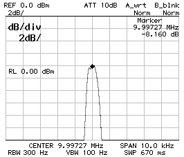
CS1 = CP2 = 680 pF ; CP1 = 560 pF
BW–3dB = 540 Hz ; BW–60dB = 4'060 Hz ; f0 = 9.997'210 MHz
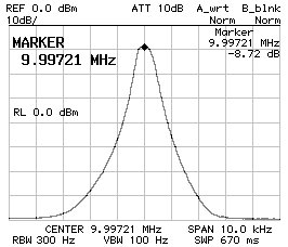
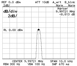
The type of crystal and the value of the capacitors determine the characteristic impedance of the filter. If the filter is not matched on its impedance, the frequency response will vary. Fortunately a reasonable impedance mismatch has little influence on the bandwidth, but has a significant influence on the pass-band ripple. In order to determine the impedance of the filter a spectrum or network analyzer is required. The easiest way is to add in series or in parallel with each end of the filter a trimmer in order to rise or drop the impedance (on one side the trimmer will be in series and on the other one in parallel). This matching method is of course lossy, but is very easily adjustable. Just adjust the two trimmers for the flattest response possible, the measure the trimmers with a multimeter and calculate the impedance.
Filter connected to 50 Ω (mismatched)
BW–3dB = 2'760 Hz ; BW–60dB = 11'520 Hz ; f0 = 9.998'530 MHz


Filter matched to 207 Ω
BW–3dB = 2'640 Hz ; BW–60dB = 13'880 Hz ; f0 = 9.998'510 MHz
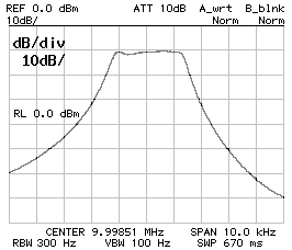

The responses above refer to a filter with CS1 = CP2 = 120 pF and CP1 = 100 pF. The extra loss due to the resistive matching is clearly visible since the flatter response is a few dB lower. All filters are four poles Tchebycheff.
| Home | Electronics | Index | Previous page | Next page |