Now let's have a look at two examples. I found two dozens of 10 MHz crystals, all from the same brand and all from the same stock. The series resonance frequency of all of them was measured and 4 crystals with series resonance frequencies within 95 Hz were found. 4 other crystals had their series resonance within 136 Hz, all the rest was spread between 9.991'974 MHz and 9.993'963 MHz. This allowed building two filters around 10 MHz, one for CW and one for SSB. When selecting crystals, it's the series resonance that matters; at least for filters with all the crystals in series as the ones described in these pages.
Using the test setup the following parameters were measured:
| fp = | 10.017'730 | MHz |
| fs1 = | 10.003'870 | MHz |
| fs2 = | 9.999'730 | MHz |
| fs3 = | 9.996'490 | MHz |
| C1 = | 10.29 | pF |
| C2 = | 33.77 | pF |
The related script found the characteristics parameters as follows:
| Cs = | 27.132 | fF |
| Ls = | 9.343 | mH |
| Cp = | 6.385 | pF |
By setting a bandpass ripple of 0.5 dB (Tchebycheff) for 4 crystals (poles) and a target bandwidth of 2.7 kHz, the simulation found the following values:
| Center frequency: | f0 = | 9.998'143 | MHz |
| Ultimate attenuation: | Uatt = | 104.9 | dB |
| Filter impedance: | Z0 = | 102.7 | Ω |
| Capacitor values: | CP1 = | 131.0 | pF |
| CP2 = | 155.9 | pF | |
| CS1 = | 155.9 | pF |
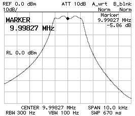
By rounding the capacitor values to the standard 150 pF and 120 pF the response of the filter was as follows (by directly connecting the filter to 50 Ω, without impedance matching):

This response is not bad, but the bandwidth is not as wide as supposed (2360 Hz instead of 2'700 Hz) and the ripple is a bit too high (about 2 dB), but by adjusting the capacitor values to 120 pF and 100 , and by finding the correct impedance of 207 Ω (see next page) the following response was achieved:
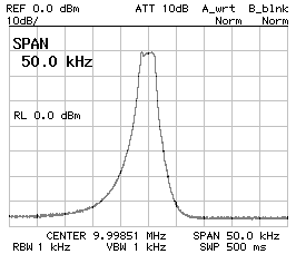
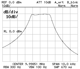

Now the filter performs as follows:
| Capacitor values: | CP1 = | 100 | pF |
| CP2 = | 120 | pF | |
| CS1 = | 120 | pF | |
| Bandwidth (-3 dB): | B-3dB = | 2'640 | Hz |
| Bandwidth (-60 dB): | B-3dB = | 13'880 | Hz |
| Center frequency: | f0 = | 9.998'510 | MHz |
The ripple in the pass-band is now 1 dB, which is still greater than what was specified, but with those crystals it wasn't possible to do any better.
By setting a bandpass ripple of 0.5 dB (Tchebycheff) for 4 crystals (poles) and a target bandwidth of 0.6 kHz, the simulation found the following values:
| Center frequency: | f0 = | 9.996'850 | MHz |
| Ultimate attenuation: | Uatt = | 159.4 | dB |
| Filter impedance: | Z0 = | 20.0 | Ω |
| Capacitor values: | CP1 = | 673.0 | pF |
| CP2 = | 801.1 | pF | |
| CS1 = | 801.1 | pF |
Since the SSB filter required smaller capacitor than calculated, it was decided to use 680 pF and 560 pF. The impedance was found to be 34 Ω and the filter performs as follows:
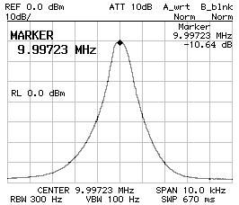
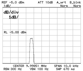
Now the filter performs as follows:
| Capacitor values: | CP1 = | 560 | pF |
| CP2 = | 680 | pF | |
| CS1 = | 680 | pF | |
| Bandwidth (-3 dB): | B-3dB = | 520 | Hz |
| Bandwidth (-60 dB): | B-3dB = | 4'360 | Hz |
| Center frequency: | f0 = | 9.997'230 | MHz |
There is no pass-band ripple and the filter is still narrower than expected, but for CW a 520 Hz filter is even better than 600 Hz.
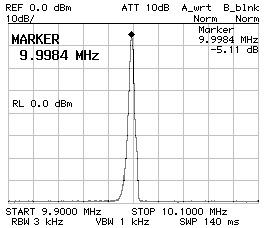
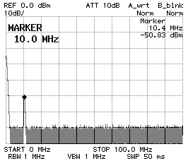
It's often told that crystal have several resonances: there is the fundamental, several overtone and some stray resonances. The question is if the filter has other stray pass-bands. The two charts below show a four poles Tchebychefffilter filter with 220 pF and 330 pF capacitors. It's clear that there are no stray pass-bands in the nearby of the desired pass-band (the figure of the shows a span of 200 kHz). It's not easy to affirm the same thing for a wider span, because the response of the filter is very sharp and the spectrum analyzer may not see a peak if this falls between two measurement points. As one can see on the figure on the right (which covers from 0 Hz to 100 MHz), there are no visible stray pass-bands, but the main pass-band appears very small and this is because of the limited amount of point of the analyzer. The peak at 0 Hz is normal behavior of a spectrum analyzer and has nothing to do with the ladder filter.
Considering that the crystals have a fundamental resonance around 10 MHz, they should also have overtone resonances roughly at every odd multiple of 10 MHz. The two charts below show the behavior of a four poles Tchebycheff filter with 680 pF and 560 pF capacitors around 30 MHz (left) and around 50 MHz (right). A resonance is there but the peak is small enough to be neglected (at least with this particular model of crystals).
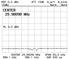
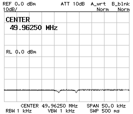
Even if it's not possible to state that there are no stray pass-bands, this is usually not a problem, since there are none in the nearby of the true pass-band and a classical LC filter is enough for removing any stray pass-band.
| Home | Electronics | Index | Previous page | Next page |