In order to design a crystal ladder filter, knowing the exact crystal
characteristics is very important.
Unfortunately the information printed on the component itself (or available on
the datasheet) is usually not enough.
Each crystal can be imagined as an RLC resonant circuit with one series
capacitance Cs and one parallel capacitance Cp (see
figure below).
The exact knowledge of Cs is mandatory for correctly designing a
ladder filter.

The test circuit below will allow measuring Cs, Ls and
Cp.
Unfortunately Rs cannot be measured with this method, but its value
is usually in the tens of Ohm.
First you need to build the test circuit a solid construction with a ground
plane will give more accurate results.
Crystal sockets should be avoided.
The use of a switch is not recommended and one should solder directly the
10 pF and 27 pF capacitors to the quartz in order to reduce stray
capacitance.
It's recommended to measure these two capacitors and use the measured values as
C1 and C2 to calculate the equivalent parameters.

This test setup is a very simple filter that will allow determining on which frequencies the attenuation is minimum (series resonance of the crystal) and maximum (parallel resonance) with the quartz alone and with 2 different series capacitors.
There are three ways of doing this: one can connect a tunable RF generator to the input and an oscilloscope on the output (or an RF voltmeter), one can connect a noise generator on the input and an HF receiver on the output, or one can use a spectrum or network analyzer. Using instruments with a resolution of at least 10 Hz is strongly recommended.
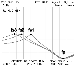
First connect the 10 pF capacitor (position 1) and look for the frequency that gives the maximum signal at the output (minimum attenuation). This will be fs1. Than connect the 27 pF (position 2) and look for the maximum output again, and this will be fs2. Now connect the crystal directly (position 3) and look for maximum output (frequency fs3) and also for the minimum one (frequency fp).

The frequency response of this filter looks something like the figure above. You will always get fs3 < fs2 < fs1 < fp. Now, just enter those values in the form below and hit the "calculate" button. For designing the filter you will need fs3, fp and Cs.
| Home | Electronics | Index | Previous page | Next page |